Raypak P-R185BL to P-R405BL Manuel d'utilisateur
Naviguer en ligne ou télécharger Manuel d'utilisateur pour Équipement pour l'eau Raypak P-R185BL to P-R405BL. Raypak P-R185BL to P-R405BL User Manual Manuel d'utilisatio
- Page / 52
- Table des matières
- MARQUE LIVRES
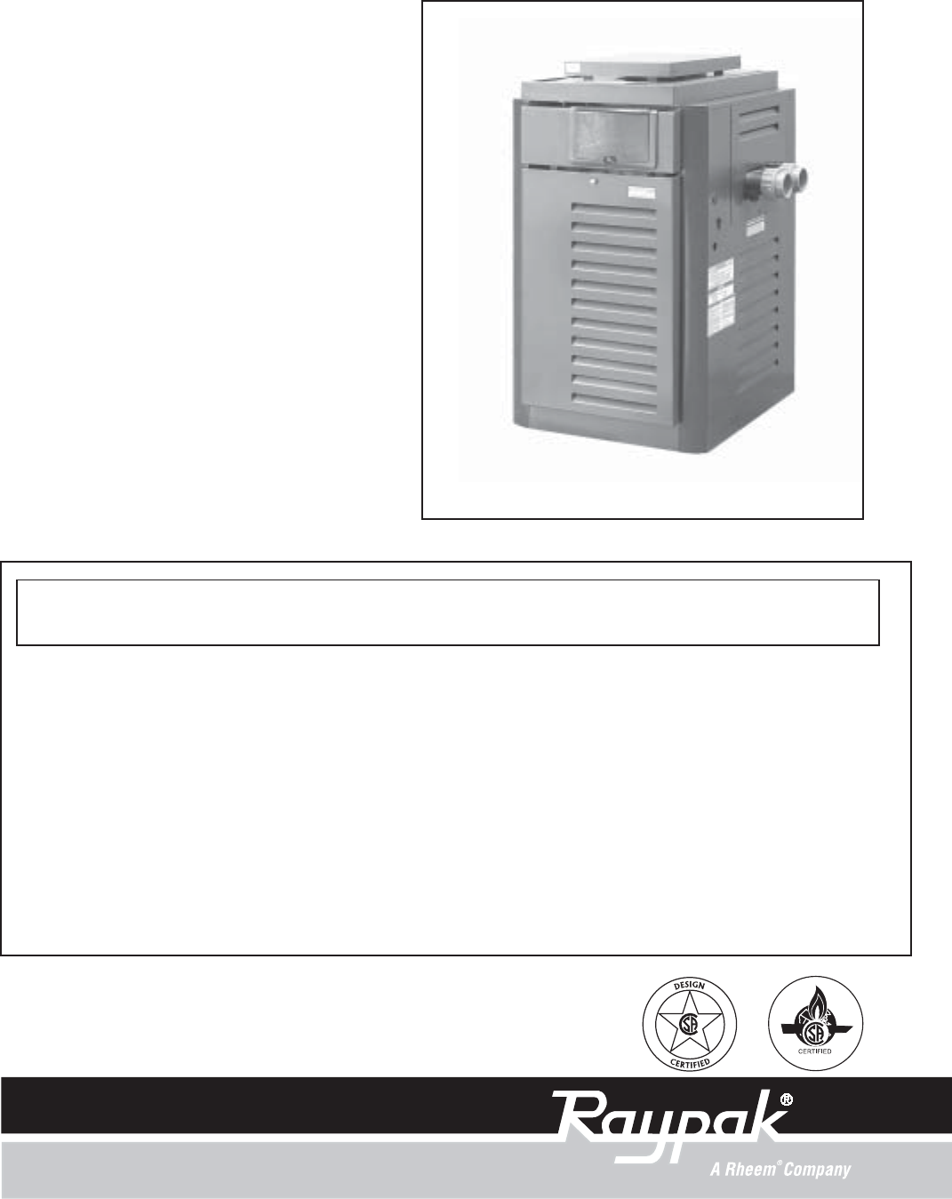
- INSTALLATION 1
- AND OPERATING 1
- INSTRUCTIONS 1
- CONTENTS 3
- PART ONE 4
- MILLIVOLT SYSTEM 5
- ELECTRONIC IGNITIONS SYSTEMS 6
- SECTION 2 - CAUTION 7
- SECTION 3 - MAINTENANCE AND 7
- CARE PROCEDURES 7
- IMPORTANT FREEZE INFORMATION 8
- Return Header 9
- Drain Plug 9
- 3. For ASME Heaters only: 9
- For ASME Heaters only 9
- PART TWO 10
- (Drafthood) Back - 6" 11
- (Water Side) 11
- (Opposite Water side) 11
- Loose with 12
- Pagoda Top 12
- (Shipped 12
- ASSEMBLY PROCEDURE 13
- Fig # 9037.2 16
- VENT PIPING 17
- Fig. #2002.1 19
- Fig. # 8095.1 Fig. # 8097.1 20
- Fig. # 8093.1 20
- Fig. #2004 21
- Fig. # 8095.0 21
- Fig. # 8150.0ss 21
- Fig.#2003 21
- ELECTRICAL WIRING 24
- 120V WIRING 25
- 240V WIRING 25
- TRANSFORMER WIRING 25
- Fig. #RP 8267 29
- Fig #2005 29
- Fig.# 9472 29
- Fig. #9473 29
- DIGITAL THERMOSTAT CONTROLS 30
- Fig# 9482 31
- Fig# 9485 31
- Fig# 9494 32
- Fig# 9480 32
- REMOTE CONTROL WIRING 33
- Adjustment 34
- PRESSURE SWITCH 34
- ADJUSTMENT RANGE 34
- Pilot Pilot 35
- Orifice 35
- Well Assembly 36
- Retainer Plug 36
- LOW NOx POOL HEATERS 37
- LOW NOx HEATERS (CONTINUED) 38
- PROBLEM CAUSE SOLUTION 39
- RAYPAK POOL OR SPA HEATER 40
- ILLUSTRATED PARTS LIST 44
- LOW NOx BURNER TRAY 45
- PILOT ASSEMBLIES 45
- Litho in U.S.A 52
Résumé du contenu
Part No. 240612CATALOG NO. 6000.52-AKEffective: 05-01-04Replaces: 03-15-04INSTALLATIONAND OPERATINGINSTRUCTIONSThis manual should be maintained in leg
SECTION 1 - RECEIVING EQUIPMENTOn receipt of your equipment it is suggested that you visually check for external damage to the carton. If the carton
12"Minimum12"Minimum4"MinimumHEATERSheet Metal24 Gauge11 IMPORTANT NOTICEThese instructions are intended for the use of qualifiedperson
Heaters must not be installed under an overhang of less than three (3) feet from the top of the heater. Three (3) sidesmust be open in the area under
INDOOR HEATER INSTALLATIONThe design is also certified for indoor installation when equipped with the approved draft hood.For Canada, indoor install
14SECURING THE TOP PANEL COVERINDOOR KIT ONLY7. Reinstall the louvered top.8. Mount the draft hood onto the adapter plate lip insidethe heater. See Fi
15INSTALLING THE TOP COVEROUTDOOR KIT ONLY22. Remove the two pieces of metal tape holding the toppanel cover up and discard.23. Insert the rear two ta
16 SPECIFICATIONS AND DIMENSIONS*Electrical Connection On Left Side is 19-1/8".a. All Air From Inside The Building:Each opening shall have a mini
VENT PIPINGVent piping the same size as the draft hood outlet isrecommended, however, when the total vent height is atleast ten (10) feet (draft hood
Fig. # 8149NOTE: Do not use Teflon tape on gas line pipe thread.A flexible sealant is recommended.A minimum of 7" W.C. and a maximum of 14"
19High temperature CPVC Header Flanges and headerFlange Nuts are provided. If there is any possibility ofback- siphoning when the pump stops, it is s
20CAST IRON HEADRERS (ASME MODELS)Heater must be located so that any water leaks will notdamage the structure of adjacent area. High temperature2"
21 PRESSURE RELIEF VALVE INSTALLATIONTo conform to local building codes, it may be necessaryto install a pressure relief valve. A 3/4" pressure
22 HEAT EXCHANGER PRESSURE DROP TABLES
231. Remove right and left side access panels (Figure 1).2. Disconnect wires at high limit, AGS (automatic gasshutoff), and pressure switch on the inl
24Option Location For LeftSide Field WiringSwayBraceBonding Lug(Standard Location)Bonding Lug(Optional Location)Fig. # 9470Control Box(Factory Mounted
25NOTE: Input power to the heater (120/240V) can be supplied from the load (pump) side of time clock or directly fromthe switch/GFCI power source. I
26 WIRING DIAGRAM - MILLIVOLT (MECHANICAL THERMOSTAT)
WIRING DIAGRAM - IID (Atmospheric)27
WIRING DIAGRAM - IID (Low NOx)28
Control PanelMounting Screws (4)Fig. #RP 8267 CONTROL ADJUSTMENTS MILLIVOLT CONTROLSThe pool or spa water temperature is controlled by thepool
CONTENTS34 PART ONEOWNER'S OPERATING INSTRUCTIONS4 SECTION 1START-UP PROCEDURES4 Before Start-Up5 Lighting Instructions & Shut-Off Procedures
30PROGRAM MODE BUTTONNotice to owner- Thermostat operationYour heater is equipped with a microprocessor controlled thermostat that controls the pool o
31 DIAGNOSTICSThe RP2100 Digital heater is equipped with on-boarddiagnostic controls. If there is a safety fault, a fault codewill be displayed along
32REMOTE CONTROL INSTALLATION AND OPERATIONCAUTION: Before installing remote controls to the RP2100 Digital Heater, read the following:The Raypak RP 2
33REMOTE CONTROL WIRINGImportant Installation Notes for Remote or External Wiring Configuration• Remote wiring must be run in separate conduit.• Remot
FLAME ROLL-OUT SAFETY SWITCHAtmospheric heaters are equipped with a thermal cutoffdevice to prevent flame roll-out in the event the heatexchanger bec
PILOT REMOVAL AND CLEANING1. Disconnect pilot tubing and wires from gas valve.2. Remove pilot assembly from burner tray.3. Remove pilot from bracket.
TUBE CLEANING PROCEDUREEstablish a regular inspection schedule, frequency de-pending on local water condition and severity of service.Do not let the
The Raypak Low NOx Pool Heaters are certified andtested under the ANSI Z21.56.CSA 4.7 standards forgas-fired pool heaters.The heater should be instal
38 BURNER DRAWER REMOVAL1. Shut off main electrical power switch to heater.2. Shut off gas upstream of heater.3. Remove front door.4. Disconnect gas l
MECHANICAL (FOR QUALIFIED SERVICE PERSONNEL ONLY)IMPORTANT NOTICE These instructions are primarily intended for the use of qualified personnel specif
4 BEFORE START-UP BURNERSClean main burners, combustion fan and air louvers ofdust, lint and debris. Keep heater area clear and free fromcombustibles
If pilot burner remains lit.Jump across pressureswitch terminalsIf main burner does notfire, remove jumperCheck for adequate waterflow from filterRepl
NOTE: Before troubleshooting, familiarize yourself with the start-up and checkoutprocedure.Check line voltage power, low voltage transformer, limit co
42 DIGITAL CONTROL LOGIC - FLOW CHART
NOTE: To supply you with the correct part it is impor-tant that you supply the model number, serial numberand type of gas when applicable.Any part re
44ILLUSTRATED PARTS LIST
45Fig. #8124Honeywell MV Fig. #8107Fig. #93696-P 3-P9-P8-P1-P5-P2-P LOW NOx BURNER TRAY PILOT ASSEMBLIES7-P9-P2-P4-P9-P7-P10-PHoneywell IID Atmospher
46
47
48
4. Push the gas control knob slightly and turnclockwise to "Off". Do not force.5. Replace heater door panel.1. Set the therm
51
Raypak, Inc., 2151 Eastman Avenue, Oxnard, CA 93030 (805) 278-5300 Fax (800) 872-9725Raypak Canada LTD, 2805 Slough Street, Mississauga, Ontario, Cana
A. This appliance is equipped with an ignitiondevice which automatically lights the pilot. Donot try to light the pilot by hand. B. BEFORE OPERA
AFTER START-UPFeel the inlet and outlet pipes. Outlet pipe should be onlyslightly warmer than the inlet. It should not be hot. VISUAL INSPECTIONWit
4. Make visual check of the burner and pilot flame.Flame pattern on the main burner and pilot is indi-cated in the previous illustration. Yellow flam
WINTERIZING THE POOL & SPA HEATERHeaters installed outdoors in freezing climate areas aresubject to be shut down for the winter. Observe thefollow
Produits connexes et manuels pour Équipement pour l'eau Raypak P-R185BL to P-R405BL
 (6 pages)
© 2020, manymanuals.fr. Tous droits réservés | 1.931 s |
 Manymanuals.com
 Manymanuals.de
 Manymanuals.fr
 Manymanuals.it
 Manymanuals.pl
 Manymanuals.cz
 Manymanuals.es
 Manymanuals-pt.com
Commentaires sur ces manuels